
[Modular 101] Matelines & Building Performance Continuity - Part 2 of 3
In Part 1 of this series, we examined thermal and moisture control at the mateline: how the inter-module gap creates thermal bridging, why maintaining insulation continuity is difficult, and how the direction of vapour drive affects moisture management in Ontario’s climate. Part 2 addresses acoustic and fire performance—the systems governed by code-mandated requirements, third-party testing, and life safety considerations.
Unlike thermal and moisture systems, which degrade performance gradually over time, acoustic and fire failures are binary: the building either meets code-required performance or it does not. Testing occurs after construction, when remediation is costly and delays occupancy. Understanding these requirements is critical before coordinating all systems in Part 3.
Acoustic Continuity: Flanking Paths and Mateline Strategies
Acoustic performance at the mateline is governed by flanking transmission, the sound that bypasses the primary demising assembly by travelling through adjacent structural elements. In modular construction, the mateline itself becomes a flanking path unless the design is properly executed.
OBC Part 5: Sound Transmission Requirements
OBC Part 5 mandates minimum acoustic performance for demising assemblies in multi-unit residential buildings:
ASTC (Apparent Sound Transmission Class) ≥ 47 for walls
AIIC (Apparent Impact Insulation Class) ≥ 47 for floors
These ratings account for flanking transmission, not just direct transmission through the primary assembly. A wall that achieves STC 55 in laboratory testing may perform at ASTC 45 in the field due to flanking through floor slabs, structural connections, or, in modular buildings, the mateline joint.
Flanking Paths at the Mateline
Sound travels through the mateline via:
Structural connections: rigid steel tie-downs and lateral braces provide direct vibration paths between modules
Continuous framing: if wall studs or floor joists align across the mateline without isolation, sound transmits through the structure
Gaps in acoustic isolation: resilient channels, isolation clips, and decoupling layers must be continuous across the joint; gaps allow sound to bypass the isolation
Testing reveals the problem: A demising wall assembly designed to achieve STC 55 may test at ASTC 42 in a modular building due to flanking at the mateline. This is below code minimum and can result in occupant complaints, re-testing requirements, and costly remediation.
Double-Wall vs. Single-Wall Mateline Strategies
Two primary strategies address acoustic continuity:
1. Double-Wall Mateline (Decoupled Assembly)
Each module incorporates a complete demising wall assembly at its edge. When modules are placed side-by-side, two independent walls are created with an air gap between them. This strategy provides acoustic isolation through mass and decoupling.
Advantages:
High acoustic performance (ASTC 50+)
Factory-installed resilient isolation (no field coordination required)
Reduced risk of flanking through structural connections
Disadvantages:
Loss of usable floor area (double-wall assemblies consume 200-250mm of plan width per mateline)
Increased module weight and cost
Potential for misalignment if modules are not placed precisely
2. Single-Wall Mateline (Shared Assembly)
Modules share a single demising wall assembly at the mateline, with acoustic continuity achieved through field-installed resilient layers or decoupling membranes.
Advantages:
Efficient use of floor area
Lighter module weight
Disadvantages:
High risk of acoustic failure if field installation is incomplete or incorrect
Difficult to achieve ASTC 47+ without rigorous quality control
Sensitive to module misalignment and structural connection detailing
In practice, most volumetric modular projects use double-wall matelines to achieve reliable acoustic performance without depending on field installation quality. While this strategy consumes more floor area and increases module weight, it provides factory-controlled isolation that is less vulnerable to site coordination failures. Single-wall strategies are typically reserved for projects where floor area efficiency is prioritized over acoustic margin, but these require rigorous field quality control and carry a higher risk of failing ASTC 47+ requirements during post-occupancy testing.
Notably, the double-stud wall assembly is available as a prescriptive design under OBC Supplementary Standard SB-3 (Fire and Sound Resistance of Walls), but only for wood-framed construction. SB-3's tables provide pre-established STC and fire-resistance ratings for double wood-stud assemblies on separate plates, allowing designers to specify a code-compliant double-wall mateline without project-specific testing.
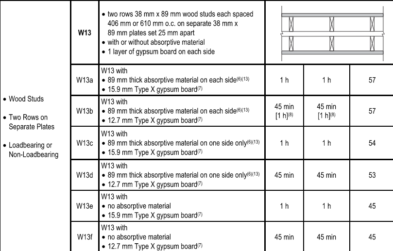
Excerpt from OBC SB-3 Table 1
This prescriptive path does not extend to steel-framed assemblies. SB-3's double-stud tables are wood-specific; there is no equivalent prescriptive steel double-stud assembly in the OBC. As a result, steel-framed modular projects must rely on tested proprietary assemblies, such as UL Design No. V464, Configuration C, a double steel-stud wall assembly recognized for its combined fire-resistance and sound-rated performance. As with all UL/ULC listed assemblies, the design must be built exactly as tested (stud gauge, depth, spacing, gypsum layer count and type, insulation placement); any deviation can void the listed fire and acoustic ratings. Where a project-specific mateline detail doesn't align precisely with the V464-C configuration, third-party fire and acoustic testing on a mockup is required to substantiate performance.
Fire Continuity: Compartmentalization Across the Joint
Fire separation continuity is the most consequential mateline challenge. Unlike thermal or acoustic failures, which degrade performance gradually, fire separation failures can lead to rapid fire spread, life-safety risks, and regulatory non-compliance.
OBC Part 3: Fire Resistance Ratings
OBC Part 3 mandates fire resistance ratings for floors, walls, and ceilings based on building classification and occupancy. For multi-unit residential buildings, typical requirements include:
1-hour fire-rated floor assemblies between dwelling units
1-hour or 2-hour firewalls depending on building height and sprinkler protection
Fire-rated shaft enclosures for vertical penetrations (stairs, elevators, mechanical chases)
When a fire-rated assembly is interrupted by a mateline, the connection detail must maintain the required fire resistance rating. This is not optional—it is a life-safety and code-compliance requirement.
Fire-Stopping at the Mateline
Fire-stopping at the mateline is achieved through:
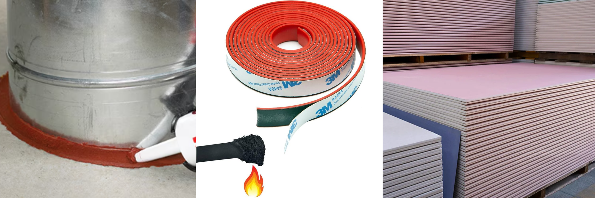
1. Field-Applied Fire Caulking
Fire-rated caulking or sealant is applied at the joint after modules are installed. The caulking must be compatible with the adjacent materials, applied to the correct depth and width, and installed per the manufacturer’s instructions.
Challenges:
Requires third-party inspection to verify proper installation
Difficult to access concealed joints (e.g., behind interior finishes)
Susceptible to installation errors (insufficient depth, gaps, incompatible materials)
May degrade over time if exposed to movement or environmental conditions
2. Intumescent Strips
Intumescent materials expand when exposed to heat, sealing gaps and preventing fire and smoke spread. Strips are factory-installed at the module edge and compress during module installation.
Challenges:
Requires precise module alignment to ensure proper compression
If modules are misaligned or gaps exceed the intumescent strip’s expansion capacity, the joint is not sealed
Cannot be visually verified after installation (the strip is concealed within the joint)
3. Continuous Gypsum Board Lapping
Field-installed gypsum board is lapped across the mateline, creating continuity of the fire-rated assembly.
Challenges:
Labour-intensive and alignment-sensitive
Difficult to execute without tolerance management and skilled trades
Often omitted or improperly installed due to site coordination failures
The Inspection Problem
Fire-rated assemblies at matelines are difficult to inspect because they are often concealed by the time the building inspector arrives. Factory certification under CSA A277 verifies that modules left the factory with compliant assemblies, but it does not verify that site-installed fire-stopping at the mateline was completed correctly.
Site inspectors may request destructive testing or third-party verification, but this is reactive—it occurs after installation, when remediation is costly. If fire-stopping is found to be deficient, the building may not receive occupancy approval until the deficiencies are corrected.
Illustrative example: Consider a modular apartment building where fire caulking at floor-to-floor matelines is incomplete. The site crew applies caulking only to visible gaps along exterior edges, omitting concealed joints behind interior partition walls. It’s an easy oversight if the mateline detail doesn't clearly call out concealed joint areas. If this deficiency is caught during final inspection, remediation requires selective drywall demolition to access the joints, installation of fire caulking, third-party inspection, and reinstatement of finishes. A delay of several weeks and remediation costs well into six figures are realistic outcomes for this scope of rework.
Conclusion to Part 2
Acoustic and fire performance at the mateline are governed by code-mandated testing and life safety requirements. Acoustic continuity requires managing flanking paths through structural connections and choosing between double-wall strategies (higher performance, greater space consumption) and single-wall strategies (space-efficient, higher risk of failure). Fire continuity requires field-applied fire-stopping that is difficult to inspect once concealed, creating verification challenges that persist until final inspection.
Both systems are binary: the building either meets code-required performance or it does not. Testing occurs after construction, when remediation is costly and delays occupancy. Unlike thermal and moisture systems, which can be modelled and predicted, acoustic and fire performance cannot be confirmed until the building is substantially complete.
Part 3 will examine the coordination challenge that arises when thermal, moisture, acoustic, and fire systems must all be resolved within the same physical joint, with conflicting spatial demands and no opportunity for sequential adjustment. Understanding how to sequence design decisions and validate through mockups is what separates competent modular practice from projects that fail performance testing.
•••
XLBench is your go-to platform for modular construction insights, setting industry benchmarks, fostering expert discussions, and sharing the latest trends. Through Benchboard, we provide data-driven research, thought leadership, and in-depth analysis to advance modular innovation.
Stay informed and be part of the conversation—follow XLBench for the latest updates, expert insights, and industry trends.
•••
xL Architecture & Modular Design (XLA) is an innovative architecture firm redefining the future of building through off-site construction technologies. With expertise in volumetric modular designs, and panelized building systems, we create cutting-edge solutions that seamlessly integrate form, function, and sustainability.