
[Modular 101] Matelines & Building Performance Continuity - Part 1 of 3
The mateline is where modular construction is most technically vulnerable. It is not a joint, but a discontinuity in every building system at once: thermal, acoustic, fire, and moisture. While conventional construction resolves these systems through continuous assemblies built in sequence, modular construction interrupts them at precise intervals dictated by manufacturing and transportation constraints. Each system has its own continuity logic, tolerance requirements, and failure mode.
Understanding how to maintain performance across the mateline is not supplementary knowledge; it is the technical core of competent modular practice.
This three-part series examines how to maintain building performance across the mateline. Part 1 focuses on thermal and moisture control, which is the envelope physics that governs energy performance and durability. Part 2 will address acoustic and fire performance. Part 3 will examine the challenge of coordinating the resolution of all systems simultaneously under conflicting spatial constraints.
What the Mateline Actually Is
In modular construction terminology, a mateline is the interface between two adjacent modules. But this simple definition obscures what the mateline actually represents: a multi-system discontinuity in which four independent building performance systems must achieve continuity despite interruptions from factory-built edges, site-installed connections, and construction tolerances.
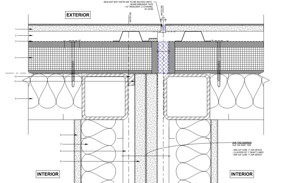
The mateline is not analogous to a construction joint in a conventional building. A construction joint is a planned interruption in a single material or assembly, such as a concrete pour joint, a drywall seam, or a roofing lap. The mateline interrupts:
Thermal envelope: insulation layers, thermal breaks, and continuous air barriers
Vapour control: vapour retarders and moisture management strategies
Acoustic separation: sound-isolating assemblies and flanking path management
Fire separation: fire-rated walls, floors, and compartmentalization systems
Each of these systems has different spatial requirements, tolerances for gaps and misalignment, and consequences of failure. Thermal bridges increase the risk of condensation and energy loss. Air leakage undermines envelope performance and pressurization control. Acoustic flanking compromises occupant comfort and code compliance. Fire separation failures compromise life safety.
The mateline must resolve all four simultaneously, within the dimensional constraints of factory-built edges and site assembly tolerances. This is not a detailing problem. It is a coordination problem with conflicting spatial demands.
Thermal Continuity: Insulation Bridging and Linear Thermal Transmittance
Thermal continuity across the mateline is compromised by two mechanisms: insulation gaps and thermal bridging through structural connections.
Insulation Gaps at the Joint
When two modules meet, their insulation layers rarely align perfectly. Factory-installed insulation terminates at the module edge, leaving a gap at the joint that must be filled in the field. If this gap is not filled, or if it is filled with lower-performance material, the result is a thermal weak point that increases heat loss and raises the risk of condensation.
In cold climates like Ontario, this risk is amplified. The mateline becomes a preferential path for heat flow, reducing the effective R-value of the assembly and creating a cold surface on the interior side of the envelope. When interior air contacts this cold surface, condensation forms. Over time, this moisture accumulation can lead to mold growth, material degradation, and envelope failure.
OBC specifies minimum insulation R-values for walls, roofs, and floors, but does not address how these values are maintained across joints. OBC SB-10 and SB-12 require effective thermal resistance that accounts for thermal bridging, but provides no specific guidance for modular matelines. The responsibility falls to the designer to detail insulation continuity and to specify field-installed materials that match or exceed the performance of factory-installed materials.
Thermal Bridging Through Structural Connections
Even when insulation gaps are filled, thermal continuity can still be compromised by structural connections that bridge the insulated assembly. Module-to-module tie-downs, lateral bracing, and shear connections are typically steel members that create direct thermal paths through the envelope.
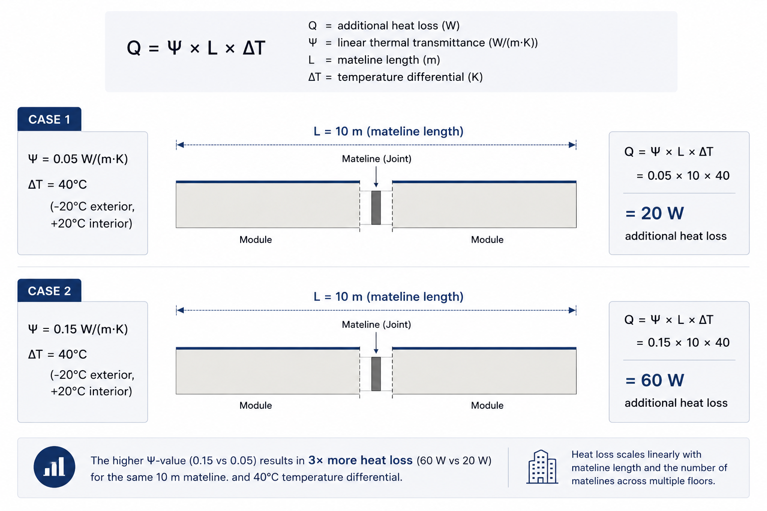
The impact of thermal bridging is quantified using linear thermal transmittance (Ψ-value), measured in W/(m·K). This value represents the additional heat flow per meter of joint length caused by the thermal bridge. While modular mateline-specific data is limited, light steel framing junctions, which share similar structural connection characteristics, typically show Ψ-values ranging from 0.01 W/(m·K) for well-detailed connections with thermal breaks to 0.07 W/(m·K) or higher for standard details without thermal break strategies. Unmitigated steel connections can produce significantly higher values, potentially reaching 0.15-0.30 W/(m·K) depending on connection geometry and the absence of thermal isolation.
A Ψ-value of 0.05 W/(m·K) across a 10-meter-long mateline in a building with a 40°C temperature differential (e.g., -20°C exterior, +20°C interior) results in 20 watts of additional heat loss per linear meter. For an unmitigated steel connection with a Ψ-value of 0.15 W/(m·K), the same 10-meter mateline results in an additional 60 watts of heat loss. For a building with multiple floor levels and multiple matelines per floor, this cumulative heat loss is significant.
Thermal break strategies for modular matelines must address the gap between modules (typically 1/4” to 1”) where insulation continuity is difficult to maintain. In modular construction, structural connections generally occur at the interior structural plane, meaning the primary thermal envelope can theoretically remain uninterrupted. However, the challenge lies in filling the inter-module gap with insulation material that matches the factory-installed R-value.
Common strategies include:
Exterior Insulation and Finish Applied On-Site: Modules are manufactured with sheathing only at the perimeter edge, and all exterior insulation (mineral wool, rigid foam, spray foam) and cladding are installed in the field after module placement. This approach ensures continuous insulation across the mateline but diminishes the efficiency gains of off-site construction, as substantial envelope work remains site-dependent.
This is the most common approach in current modular practice, but it sacrifices schedule and cost advantages. If 30-40% of envelope work occurs on-site, the time savings from factory fabrication are reduced, and the project becomes vulnerable to the same weather delays and site coordination challenges as conventional construction.
Compressed High-Performance Insulation at the Gap: Field-installed spray polyurethane foam (SPF) or mineral wool is applied within the gap between modules to bridge the insulation layer. This requires precise module alignment and careful execution to avoid thermal bridging at compressed areas. Achieving an equivalent R-value in a 1” gap to that of a 6” factory wall assembly is difficult, often resulting in reduced effective thermal performance at the joint.
For example: A factory wall assembly with R-24 insulation (nominal 6 inches of mineral wool) interrupted by a 1-inch gap filled with spray foam (R-6 per inch) results in a localized R-6 section. The thermal bridging effect of this reduced insulation creates a cold spot, even though the gap is "filled."
Integrated Facade Systems: Unitized curtain wall systems (such as Uniti Wall or similar panel systems) are designed with gaskets, thermal breaks, and prefabricated insulation that accommodate modular tolerances. These systems treat the mateline as a designed joint rather than a construction gap, providing factory-controlled thermal continuity that is compatible with modular assembly sequencing. This approach maintains the benefits of off-site fabrication while achieving continuous envelope performance.
Unitized systems are more common in mid-rise and high-rise modular projects where envelope performance and speed are both critical. The system cost is higher than site-applied insulation, but the schedule certainty and performance consistency often justify the premium.
Minimizing the Gap Through Tolerance Management: Specifying tighter module fabrication tolerances (e.g., ±3mm instead of ±6mm) and using precision foundation systems reduces the inter-module gap width, making field-applied insulation more effective. However, this strategy requires higher manufacturing precision and increases cost.
In practice, many modular projects do not calculate Ψ-values at matelines, relying instead on prescriptive insulation requirements. Without thermal modelling, projects often default to site-applied exterior insulation strategies that meet minimum code compliance but sacrifice the schedule and cost advantages of off-site envelope construction. The challenge is not eliminating thermal bridging through structural connections. It is maintaining continuous, high-performance insulation across the physical gap between modules while preserving the benefits of factory fabrication.
Vapour and Air Continuity: Alignment, Direction, and Condensation Risk
Vapour control and air control are related but distinct systems. Both must be continuous across the mateline, but their continuity requirements differ.
Air Barrier Continuity
The air barrier prevents uncontrolled air leakage through the building envelope. Air leakage carries moisture, undermines insulation performance, and increases heating and cooling loads. All building codes require air-barrier continuity, and, for example, OBC SB-12 mandates that air leakage for new housing construction be no more than 2.5 ACH@50Pa for houses and 3.2 ACH@50Pa for multi-unit residential.
At the mateline, air barrier continuity is achieved through field-applied sealing such as:
Self-adhered membranes lapped across the joint
Spray-applied air barriers extending from one module edge to the adjacent module
Gaskets or backer rods with compatible sealants applied at the joint
The challenge is alignment. If modules are misaligned by even 10-15mm, the air barrier may not lap properly, creating gaps that allow air leakage. Site conditions, such as cold temperatures, wet substrates, and contaminated surfaces, further complicate field application. Air barrier materials that perform well in controlled factory conditions may not adhere properly when applied on-site in sub-zero temperatures.
Blower door testing after module assembly can identify air leakage at matelines, but by this stage, remediation is difficult. Modules are fully enclosed, and accessing the mateline joint may require selective demolition of interior or exterior finishes.
Vapour Barrier Continuity and Vapour Drive Direction
The vapour barrier (more accurately, vapour retarder) controls moisture diffusion through the envelope. Most Canadian building codes require vapour barriers on the warm-in-winter side of insulated assemblies to prevent interior moisture from diffusing into the insulation cavity, condensing on cold surfaces, and accumulating.
At the mateline, vapour barrier continuity is typically achieved by lapping polyethylene sheets across the joint, with overlaps sealed using acoustical sealant or compatible tape. However, this assumes that:
The vapour barrier is accessible at the module edge (often it is not as interior finishes may already be installed)
The overlap is sufficient to accommodate module misalignment
The sealant remains effective over the building's lifespan
Vapour drive direction complicates this further. In Ontario’s cold climate, vapour drive is predominantly outward during winter (from warm interior to cold exterior). However, during summer, vapour drive can reverse, particularly on air-conditioned buildings with dark cladding exposed to solar radiation. If the mateline detail includes both a vapour barrier on the interior and an impermeable exterior cladding with no drainage or drying capacity, moisture can become trapped in the wall assembly.
For modular buildings with metal cladding, this trapped moisture has no escape path. The result is concealed condensation, insulation degradation, and potential mold growth.
To minimize this effect, using hybrid vapour control strategies is best practice. Some strategies include:
Variable permeability membranes that allow drying in both directions, depending on humidity conditions
Vented rainscreen cladding that provides a drainage and drying plane behind the cladding
Vapour-open air barriers on the exterior side, allowing outward drying while maintaining air tightness
These strategies are well-established in conventional construction but are rarely specified for modular matelines, where detailing tends to default to prescriptive polyethylene vapour barriers without consideration for bidirectional drying.
Conclusion to Part 1
Thermal and moisture continuity at the mateline is foundational to envelope performance. The inter-module gap, typically 1/4 inch to 1 inch, creates thermal bridging and insulation discontinuity that must be addressed through strategic detailing: site-applied exterior insulation, compressed high-performance insulation, unitized facade systems, or tolerance management.
Air barrier continuity requires field-applied sealing that accommodates module misalignment and site conditions. Vapour barrier continuity must account for bidirectional vapour drive in climates like Ontario’s, avoiding trapped-moisture assemblies that create concealed condensation risk.
Without thermal modelling and moisture analysis, modular projects default to prescriptive details that meet minimum code compliance but often sacrifice the schedule and performance advantages of off-site construction. Understanding the thermal and moisture physics at the mateline is the foundation. Part 2 will examine acoustic and fire performance, the systems governed by code-mandated testing and life safety requirements.
•••
XLBench is your go-to platform for modular construction insights, setting industry benchmarks, fostering expert discussions, and sharing the latest trends. Through Benchboard, we provide data-driven research, thought leadership, and in-depth analysis to advance modular innovation.
Stay informed and be part of the conversation—follow XLBench for the latest updates, expert insights, and industry trends.
•••
xL Architecture & Modular Design (XLA) is an innovative architecture firm redefining the future of building through off-site construction technologies. With expertise in volumetric modular designs, and panelized building systems, we create cutting-edge solutions that seamlessly integrate form, function, and sustainability.